The amp has been designed to be an ideal upgrade for builders wishing to step up from Gainclones. This amp will kick out the power where Gainclones fall over, yet still maintain a sweet sound. The use of n-channel MOSFETs in the output makes the amp easy to source parts for as well as being very rugged. Provided that high power MOSFETs such as the specified IRFP250 are used and the appropriate fuses are used on the board, the amp should shrug off short circuits at the output.
With the recommended supply voltage of 41 V per rail (30 V transformer secondaries), 160 W RMS into 4 ohms is achievable, again if the recommended IRFP250 devices are used. The use of less powerful MOSFETs will mean you are limited to 8 ohm loads and/or reducing the rail voltage.
Note that IRFP250N or IRFP250M devices are not recommended, they are a newer generation than the original IRFP250 and as such have a smaller die which cannot take the stresses of linear operation as well and may be unreliable unless you limit use to 8 ohm loads and/or reduce the rail voltage. Fairchild FQA32N20C is a good alternative.
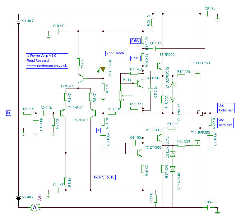
The bias generator (T6, R11, P1, R12) is configured so that if the potentiometer goes open circuit, bias current will fall to a small amount. The Zener diodes on the MOSFETs are to protect them from over-voltage which can 'punch through' the gate destroying the device. The corresponding diodes in series with them prevent any back EMF from the load turning the MOSFET on.
The output stage Boucherot cell (often called Zobel network) consisting of R21 and C7 provides frequency dependent compensation for the output stage and for it to perform as intended a metal film resistor should be used as these have little to no inductance. Under normal conditions very little power will be dissipated in this resistor so 2W is fine. If this resistor gets hot then it is a sign that the amp is oscillating.
Note that the PDF of component side shows R11 as 6.2k, this should be 4.3k as shown on the schematic.
Also, R13 and R14 are shown as 2.4k, these have been revised to 2.7k as shown on the schematic. The pad spacing for them is slightly further apart than the other resistors to accomodate the 0.5W size.
 PDF of copper side of PCB
PDF of copper on component side of PCB (optional)
Do not fit the fuses, instead fit 100 ohm 1 watt resistors in their place. These 'safety resistors' will limit current in the event of a fault and prevent the amplifier blowing up. Fuses will not act quick enough if there has been a build error.
Do not connect any input signal nor any load on the output.
Turn the bias preset potentiometer as far anti-clockwise as possible, do not force it. If you wish to set and check this prior to soldering it into the PCB, orient the preset potentiometer so that the middle pin is higher than the outer pins. Now measure the resistance between the middle pin and the rightmost pin, it should be less than 50 ohms.
Connect an ammeter in series with the negative rail. Apply power and note the reading on the ammeter, it should be less than 20mA. The 'safety resistors' should also be cool. If either of these is not true, remove power immediately and check the bias preset potentiometer is wound to minimum. If it is then begin to look for solder bridges, broken tracks, dry joints and wrong components, etc.
If all seems OK then proceed to turn the bias preset potentiometer clockwise and you should see the current increase. Set it to 75mA then keep checking the current every minute to make sure it is not running away - it should not reach 100mA within 2 minutes, if it does then turn it down to 75mA again. There will be some movement whilst thermal equilibrium is reached so do not worry too much. Thermal equilibrium should be reached by about 15 minutes, depending on the heatsink. Do not attempt to connect a loudspeaker or play any signals as the 'safety resistors' will prevent the amplifier working in this way.
Once the bias current has been set you can check the output of the amp to make sure that the DC offset is less than 50mV. If it is more than 1V then there is a fault with the amplifier so check for solder bridges, broken tracks, dry joints and wrong components, etc.
Now that everything has been checked you can remove power and replace the 'safety resistors' with the correct rating fuses and re-check the bias procedure above (the bias current will raise a little due to no longer having resistors in the rails) then the amplifier is ready for use. It will not require further adjustment unless a different rail voltage is used or the heatsink is changed.
All content on this website Copyright © 2005-2026 Richard Read, unless otherwise stated. For commercial use please contact me.