Read Research logo
 
Home Projects Utilities Articles Bespoke Shop Links Communication

Soft Start

Introduction

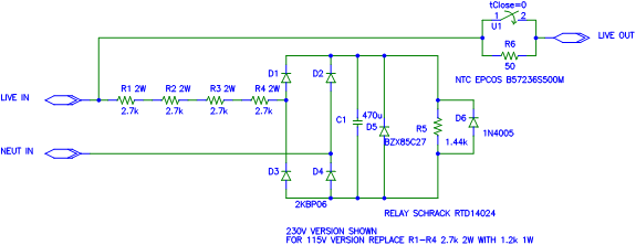
This is a really simple, but effective solution to big inrush currents on start-up. It is fail-safe as it uses a negative temperature coefficient (NTC) thermistor to limit the current so if the relay fails no damage to either the switched appliance nor the soft start itself should occur. It also resets quickly so should provide protection again even straightaway after the appliance has been turned off. The delay before the relay closes is about 0.25 seconds.


Schematic

Schematic


Circuit Operation

The mains is passed through the four resistors to drop the voltage to around 24V, which reduces the stress on the bridge rectifier. I have still specified a 600V bridge though to satisfy worst case fault conditions. The AC is then smoothed by the capacitor and the zener diode acts as a voltage limiter in case of spikes and short term voltage increases in the mains. The resistance of the input resistors in conjunction with the smoothing capacitor provides a rising voltage to the circuit, so that by the time the voltage has risen high enough to energise the relay a few hundred milliseconds have passed. The relay then bypasses the NTC to allow the load to draw full current.


Printed Circuit Board

I recommend the use of nylon 12mm spacers to mount the PCB on so that you can achieve good insulation clearance between mains live parts and chassis. It is also important that you raise the four input resistors and the zener diode up off the board by 6mm or so to aid their heat dissipation. If you fail to do this the PCB will char over time and you may develop issues with bad joints.

PCB Copper PDF of copper side of PCB

PCB Component PDF of component side of PCB


All content on this website Copyright © 2005-2024 Richard Read, unless otherwise stated. For commercial use please contact me.