Ideally, for the drive unit measurements the loudspeaker should be clamped/bolted to a vertical open frame, away from any walls and floors, but this is unwieldy and impractical for most people, as well as needing to be extremely sturdy and stout for today's high quality sub-woofer drivers. I just set the drive unit down on its magnet, on a small but solid table. I put three equidistant blobs of Blu-Tack on the magnet to keep it secure. For drivers with vented pole pieces, I stand the magnet off the surface using much larger blobs of Blu-Tack to allow airflow in and out of the vent. A drainpipe drilled with plenty of large holes could also be used. I have also heard of people standing the drive unit on the edge of a table vertically as it would be on a baffle, resting on its magnet and then being clamped from the magnet to the table, but I have not tried this.
The test set-ups described in the following text are used for all tests. They offer a way of measuring and recording the impedance curve of a loudspeaker. From this information the Thiele-Small parameters can be derived.
Voltage source is where you try to drive the loudspeaker as "directly" from the amplifier as possible, so the voltage applied to it is constant (note I don't mean constant like DC - which would quickly burn out your voice coil, I mean that the applied voltage stays the same regardless of the changing impedance of the voice coil). The best way to implement this method is to measure the voltage across a low value (typically 0.1 ohms) "current measuring" resistor in series with the loudspeaker (as shown in Figure 3, below). It is not recommended that you use an ammeter for this purpose because some ammeters may change range part way through the experiment which will cause a change in the impedance of the circuit, hence your results will be inaccurate.
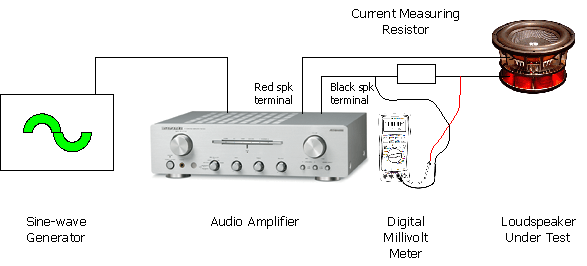
Figure 3: Voltage Source Method.
Current source is where the current fed to the loudspeaker is constant (note again as above this is not like DC). This can be achieved in a basic fashion by simply "swamping" the loudspeaker impedance by a relatively high value "current source" resistor (as shown in Figure 4, below).
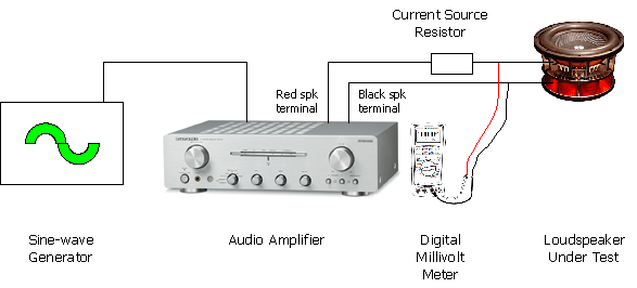
Figure 4: Current Source Method.
Because of the potential divider action of the "current source" resistor and voice coil impedance, an amplifier capable of clean output at 65 watts RMS into 8 ohms should be used with a 2.2k "current source" resistor to ensure adequate drive voltage. If you have a lower powered amplifier you will need to reduce the resistance otherwise you will not achieve enough voltage swing and clip the amplifier, ruining your results. The table below offers some guidelines on "current source" resistor choice for a range of amplifier RMS powers into 8 ohms.
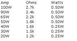
Table 1: Current Source Resistors.
You will get more accurate results with higher value "current source" resistors as the "swamping" effect is greater, so try to use the highest powered amplifier (and consequently "current source" resistor) that you can.
I prefer to use the current source method for a number of reasons:
You can download a neat and simple little sine wave generator from the Utilities page of the website. This handy tool allows you to increment the frequency up and down in various step sizes. The advantage is that you can tweak the frequency accurately and easily, and see the true value displayed on the screen. So you don't need to have an oscilloscope or frequency meter to determine the true frequency, like you would if you used a traditional standalone signal generator.
As I prefer the current source method I will only go into detail on measurements using that method. The same methods apply whether you are using a conventional amplifier and "current source" resistor or my true current source module.
All content on this website Copyright © 2005-2026 Richard Read, unless otherwise stated. For commercial use please contact me.