Note that this guide will ensure you have a hum free amp. What it cannot do is ensure your system is free of ground loops, because they are a byproduct of using unbalanced interconnects. If your amp with nothing but a speaker connected to it is silent, but when you connect a source it hums, then you need some way of breaking the ground loop between the components. Balanced inputs and outputs, or an input transformer on the amp, will fix it.
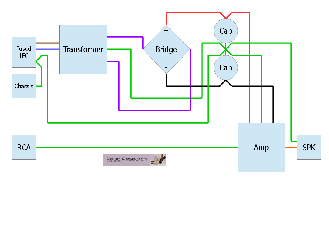
Figure 1: Wiring Diagram.
Fused IEC - fused IEC 60320 C14 mains inlet. This has 3 terminals; live (blue), neutral (brown), earth (green). Connections should be soldered then insulated with heatshrink, or fully insulated crimp terminals used.
Chassis - M4 bolt used solely for the connection of protective earth to chassis. This should be a short wire of at least 30/0.25 or 16AWG thickness. Put the bolt through the chassis then add a shakeproof washer, next add the earth wire ring terminal followed by another shakeproof washer. Finish with a nyloc nut.
RCA - input RCA/phono connector. This should be a type that is insulated from the chassis otherwise a ground loop may be created.
The transformer shown in Figure 1 has a single primary winding. If yours has a dual primary winding, you will need to wire them in series for 230V countries or parallel for 115V countries. It is important that you get the start and finish of the windings the correct way round or the transformer may cook. The start is usually denoted by a dot. See the diagrams below.
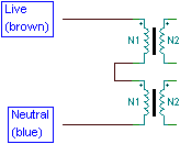
Figure 2: Series connected primaries for 230V countries.
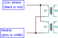
Figure 3: Parallel connected primaries for 115V countries.
The transformer shown in Figure 1 has a centre-tapped secondary winding. If yours has a dual secondary winding you need to connect the finish of the first winding to the start of the second winding, and this becomes your centre tap. See the diagram below.
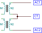
Figure 4: Dual secondaries connected to form a centre tap.
I have shown a single bridge rectifier in Figure 1. Some people like to use dual bridge rectifiers, but this is not possible with a centre-tapped secondary. Even with dual secondaries, I don't think it's worth doing - it just adds cost and wastes space. Another thing some people like to do is put caps across the diodes, thinking they are going to snub some ringing. All it does is create a bypass for high frequencies to get in to your PSU, so not a good idea. Any snubbing will require test equipment to find the correct value cap to suit your particular implementation, and it is usually best just across the transformer secondary.
The wiring of the caps is an important detail. The exact midpoint of the caps is your star ground, and you must use the exact midpoint or you will suffer from charging pulses in your ground. Some people like to connect smaller value bypass caps across the main caps, I advise against this as in this position they will either be useless or create a resonant circuit at high frequencies. The correct place for them is close to amp rails or chip pins.
The amp itself should have screened cable at its input to the RCA/phono socket. The Boucherot cell (often mistakenly called Zobel network) should be on the amp PCB to remain effective. The output wire should go to the speaker connector, and the ground for the speaker connector should be taken from your star ground point.
To add another amplifier channel, the connections should be taken from the capacitors and star ground. Remember, even thick wires have a little resistance!
It goes without saying that the PSU projects and amp projects on this website all comply with the design rules given above. So if you use those it's all plug and play.
All content on this website Copyright © 2005-2025 Richard Read, unless otherwise stated. For commercial use please contact me.